
The window should open with the "selected" box checked. Then you right-click one of the highlighted components and select "find similar". They should highlight, as in the top pic. You don't get to check the "selected" option, it gets checked for you.įirst of all you select them on the PCB by left-clicking and dragging a box around them. In previous protel, we select the necessary components and do a global change with the option 'Selected' ticked. The problem is when I am not able to select these group of LED. In my illustrations below, you'll see at first I select an area containing several LEDs, then I check "same" for "footprint" and "selected". There is a box at the bottom of the "find similar" box marked "selected".
ALTIUM UNKNOWN PIN ERROR UPDATE
Finally, if I have change the PCB library footprint and wanted it to update to the pcb file, how do I do that? You can see "inspector" window. Everytime I select, all of the 10 LED's pad are selected. Let say I have wanted to change the pad for 5 of the 10 LED's.
ALTIUM UNKNOWN PIN ERROR PDF
Can I ask you one more question? I've just read the ' Find Similar Objects ' pdf but I still not able to select a particular group of components. There's a Protel forum similar to this one, very helpful people, and if anything doesn't get answered right away an Altium FAE shows up with a solution. This lets you match the unidentified components and it won't bother you again. Do the update anyway, then from the PCB view, open the Project dropdown, then select "component links". When you do the update you'll often get a message like "Failed to identify 2 components. By the way, I like your picture of cherry? I am using Protel DXP I was going to suggest that.Īlso, sometimes the update will fail on part of the changes, usually the nets, and running update a second time will bring up just these items and succeed.
ALTIUM UNKNOWN PIN ERROR MANUAL
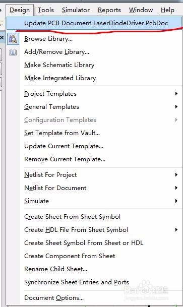
If anyone have any ideas of some user manual that explains these error messages, please do inform me. I have added some new components to the existing schematic. Controls for the Online reporting are available on the Schematic - Compiler page of the Preferences dialog.I encounter this message while trying to transfer a schematic to a existing PCB layout. It is, however, used by the Online (real-time) error reporting, directly within the design workspace. The Report Mode setting on the Error Reporting tab of the Options for Project dialog has no affect on the Report Mode setting that appears for a violation of this type in the Messages panel.The actual report mode used for a violation of this type is dependant on the specific object type, its electrical I/O type, and the corresponding reporting level defined on the Connection Matrix tab of the Options for Project dialog ( Project | Content | ).The identifier for the pin will be listed in that message. When the unconnected object is an input pin, an additional violation message will appear alerting you to the fact that the net to which the pin is associated contains floating input pins.Place No ERC directives on unused input or output pins.Tie any unused input pins to the appropriate power line.If a port or sheet entry is redundant, remove it from the design.If the pin/port/sheet entry is to be used, ensure that it is wired up to the rest of the circuit accordingly.Recommendation for ResolutionĬonsider the following in order to resolve this error: Locationis the X,Y coordinates of the object on the source schematic sheet. Objectis the type and name of the offending object (pin, port, or sheet entry). A notification is also displayed in the Messages panel in the following format: If compiler errors and warnings are enabled for display on the schematic (enabled on the Schematic - Compiler page of the Preferences dialog) an offending object will display a colored squiggle beneath it.

This violation occurs when a pin, port, or sheet entry object, is not wired up to the rest of the circuit. Parent category: Violations Associated with Nets


 0 kommentar(er)
